Part 4: Engineer's Corner #1: The Basics
Engineer’s Corner 1: The BasicsI got a lot of comments to the last post where people said that they had no idea what those screenshots I was posting were supposed to mean. I’m starting this series of posts to explain what’s going on.
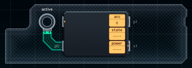
These screenshots are from my chip design simulator, ConceptCAD. The labeled circles in the prototype board are inputs or outputs that I can get / send a signal to if I hook up a part to it with a wire. The green things are, you guessed it, the wires.
This chip is the MC4000 microcontroller I was talking about before, and the straight lines on its side are pins (note the labels). The MC4000 can read signals from pins or write signals to them, if I tell it to with the right instruction (and the pin is connected to something meaningful by a wire).
The space on the left of the MC4000 is for instructions. I can have up to 9 lines of code, which doesn’t sound like a lot! Spoiler: it’s really not. When a MC4000 is turned on, it will follow its programmed instructions forever in a loop.
So far, the instructions I’ve had to use are:
• mov - push a value somewhere, or copy a value from one place to another
mov value dest
mov source dest
• slp - wait for a set number of time units
slp time
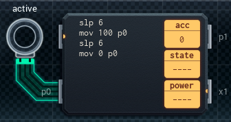
This is the MC for the power light of the fake security camera. The mov instructions in the image push a specific value out to p0, which then travels along the wire from p0 to the output that leads to the active LED.
The instructions start by telling the MC to wait six time units (slp 6). Then, by pushing 100 to p0 (mov 100 p0), I turn the LED on. I wait six more time units (slp 6) and then turn the LED off. (mov 0 p0) This repeats forever.
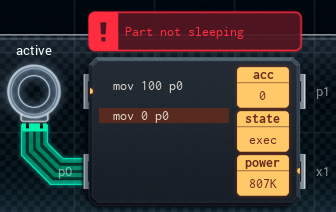
(As an aside, every MC4000 has to have at least one instruction that makes the part wait for a period of time - or to put it another way, every MC has to have a slp instruction somewhere in its instruction list. MCs process really fast, and if you don't add a timed wait, the chip will consume infinite power, create a black hole, and forge a new universe.
Also, if I don’t put in a slp instruction in a MC’s code, the simulator will throw an error. :P
There is one other instruction that sleeps a MC - slx - but I don’t fully understand that one yet, so we’ll talk about it later.)
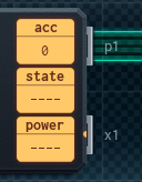
A few more bits of the MC I haven’t talked about yet: the accumulator (acc for short) is a register, which is a fancy way of saying that it’s a box I can store numbers in. I could, for example:
• put the number 3 into acc (mov 3 acc),
• move a value received on the MC’s pin p1 into acc (mov p1 acc),
• push a value from acc out to pin p1 (mov acc p1),
...and so on.
There’s also several instructions that modify the value in acc, but we’ll cross that bridge when we come to it.
Finally, “state” and “power” are used while the simulation’s running, to show if the MC’s active or waiting, and also how much power it’s using (MCs draw full power when active, but not when waiting). This might get relevant if I ever get a job that needs to go easy on a device’s batteries.
That's the basics! I'll add new "Corner" posts if I run into any more concepts that might trip people up.